Categories
Most CNC controls do not support regular Cutter Diameter Compensation (G41/G42) for 3D toolpaths. The only way to compensate for a worn 3D finishing tool is to use 3D Cutter Compensation. On FANUC controls, this feature is supported with the following codes: G41.2 (3D COMP LEFT) and respectively G42.2 (3D COMP RIGHT). This type of cutter compensation performs 3-dimensional compensation in a plane (compensation plane) perpendicular to the tool vector.
Example:
N124 G42.2 G1 X3.3018 Y5.7128 Z8.5 A-11.066 C28.92 F150.
N125 X3.2936 Y5.8103 Z8.4825 A-11.385 C27.853
N126 X3.2712 Y6.2005 Z8.4108 A-11.698 C26.435
In order to output the G41.2 or G42.2 codes based on the direction of compensation, three settings are required when configuring the post. First, the G-code register must be defined to support a decimal point. Second, the “3D Tool Comp” section of the Questionnaire must be defined a certain way. Finally, a User Defined Syntax macro has to be added in the “Customization” section of the Questionnaire.
- Register definition:
The register used for G-codes must be defined with up to 2 integer places and 1 decimal place. The decimal point must be set as optional, so that it will be output only if necessary. The resulting format of the G-code register will be: ‘Gs2f1’. - The “3D Tool Comp” section:
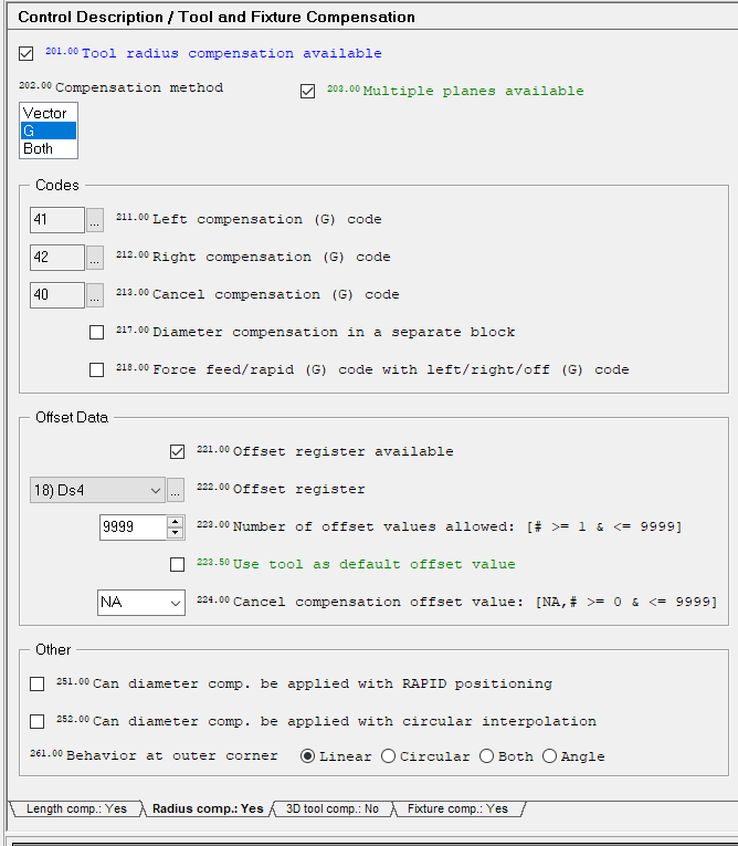
The Control Description / Tool and Fixture Compensation / 3D Tool Comp section can be defined as illustrated below.
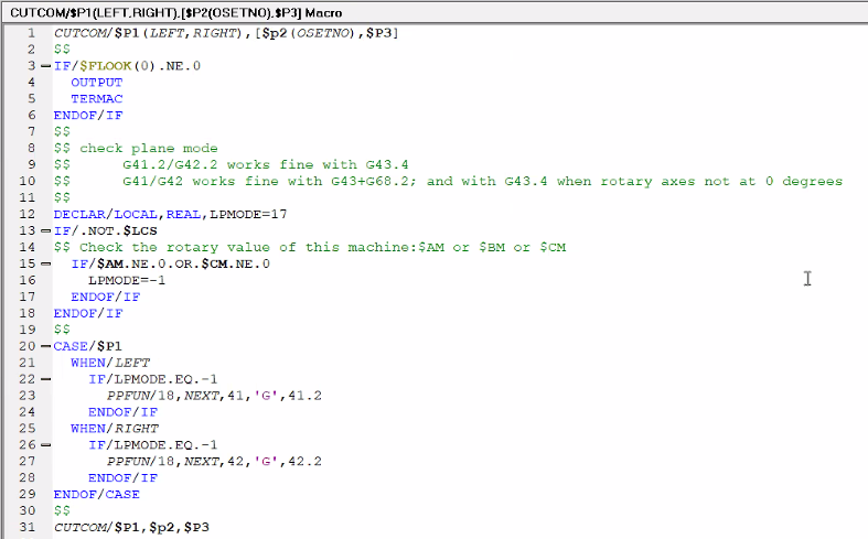
- User Defined Syntax Macro: Write the following User-Defined Syntax macro on the major word CUTCOM
Benefit to User
Control the direction (left / right) for applying 3D compensation using codes G41.2 / G42.2 with G43.4 on FANUC controls.
For more information or comments, please do not hesitate to contact TechTipTuesday@icam.com